The Amoeba King
This page contains helpful information regarding a single-key PCB dubbed the “Amoeba King”, useful for wiring up mechanical keyboards, Dactyl Manuforms in particular. If you’re looking for information on King Amoeba from SpongeBob SquarePants, this… This is not that and I’m unsure of how to help you.

The Kings have some tricky foibles that need some explanation, at least more than you’ll find roaming the outer reaches of Reddit and Google.
One: SMD
Except for the key switch, everything on the Amoeba King is SMD: the Kailh sip sockets, the diodes, and the LEDs. SMD soldering can be tricky. There are those who brave it with regular solder wire and a soldering iron but, personally, speaking as a coward, I use solder paste and a hot air rework station. A cheapo soldering microscope is a huge help, too.
For the SMD diodes and LEDs, a great tactic is to NOT break apart the Amoebas but keep them connected until LEDs and diodes are soldered. It’s much easier to run a little assembly line this way instead of soldering them one by one where they’ll just skitter around while you try to work.
Two: Kailh Hot Swaps
These SIP sockets are relatively easy. Best practice is to solder them with the Amoeba in the case with the switch inserted on top so you can ensure the switch posts fit nicely into the Kailh socket. It’s a tad tricky, but doable.
There’s an outline on the Amoeba indicating where they should be. Relatively easy to solder into place with an iron.
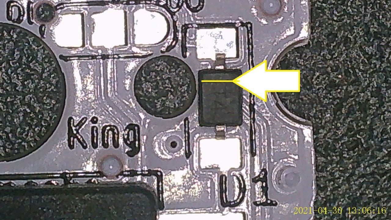
Three: 1N4148 SMD Diodes
SOD-123 or SOD-323 will both fit and you’ll probably maintain a little extra sanity with the larger 123s. When looking at the Amoeba face up, the diodes go onto upper and lower pads marked off with a D1 to the right of the center post hole. The line on the diode should orient towards the UPPER pad and the top of the Amoeba. You can tell which is up and down by the orientation of the text.
Five: RGB LED Matrix
Here’s the trickiest bit. V (power) and G (ground) on the LED matrix can be more-or-less routed as you need, as long as every Amoeba gets both from the controller.
It’s the signal that’s tricky. It needs to snake through the matrix in a chain, not a matrix. To make it easier (or not), the Kings let you select the direction the data signal should travel by connecting two pairs of pads with a dab of solder. At the top of the central post hole and to either side are three pads.
On both sets, if you connect the center and RIGHT pads, the signal flows to the right (from D1 on the left side to D2 on the right).

If you connect the center and LEFT pads, the signal flows to the left (from D2 on the right to D1 on the left).

Here’s a full 3x2 matrix.

On the direction pads, the pink dot represents the connecting drop of solder. On the top row, the middle and right pads are connected, so the signal moves to the right, from D1 on the top left Amoeba to D2 and then to D1 on the next Amoeba, all the way to the top right Amoeba.
BUT, note that the connection then goes from the D2 of the top right Amoeba to the D2 of the bottom right Amoeba. The lower row has the connection on the middle and left pads, so the signal moves to the left, so D2 on THAT row is the input and D1 the output.
Still confused? I sort of hope so! I sure was at the beginning, but I hope this helps make some sense of it.
But feel free to reach out to us if you need any help.
Four: SK6812MINI-E LEDs
These aren’t TOO tricky. Looking at the Amoeba King with the side that has the SMD pads and the hole for the LED at the top. Place the LED FACE DOWN, so the light goes towards the opposite face of the Amoeba and the SMD leads sit on the pads on the top face. The notched connector on the LED is GND which should go onto the lower left pad. In the picture below, GND is circled in red at the lower left.
